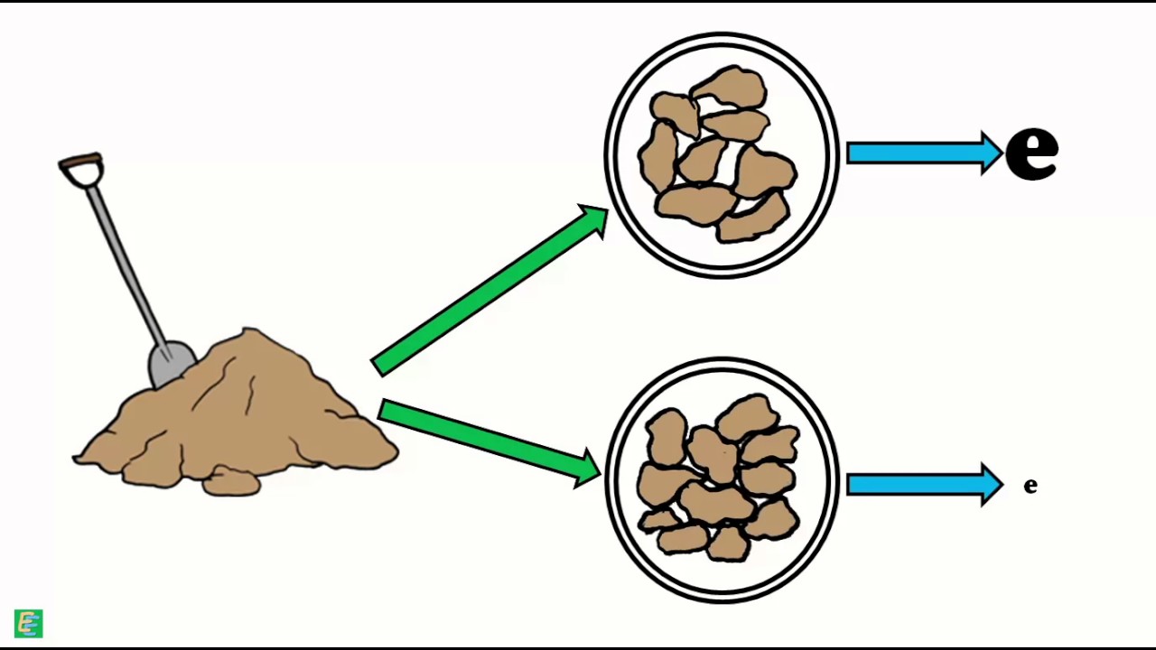
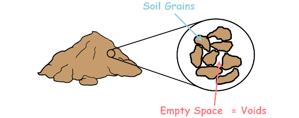
A soil mass is composed of small solid particles which we call the soil grains. These soil grains when depositing in a soil mass arranges themselves in a way that some amount of empty space is enclosed between them. We call these spaces voids. Water can flow though these voids.
The property of the soil which permits the water or any liquid to flow through it through its voids is called permeability. Permeability is the ease with which water can flow through the soils.
We have analysed the flow of water in both isotropic and anisotropic soil and have learned to construct the flow net in our previous posts. Isotropic means having identical values of a property in all directions and anisotropic means different properties in different directions.

Sometimes it becomes a necessity to use two different soils to make a soil structure. By two different soils, we mean they have different properties like different permeability, different void ratio, different unit weights etc.
In such cases the permeability of the soil changes suddenly along the flow paths and the flow lines and equipotential lines of the flow net get deflected at the junction point of the two soil masses. Consequently, our flow net gets modified.
The phenomenon of deflection of the flow lines is somewhat similar to the refraction of light rays. We know that when light enters from the rare medium to a dense medium it gets deflected towards the normal. Similarly flow lines get deflected towards the normal if the flow is from rare medium to dense medium that means when flow is from highly permeable medium to less permeable medium.

While when water flows from low permeable medium to high permeability medium it gets deflected away from the normal.

To analyse such a flow, let us begin by considering the two soils of coefficient of the permeability k1 and k2 meeting each other in a soil structure.
Now either k1 may be greater than k2 or it may be less than k2. We will consider both the cases one by one.
k1 > k2
Flow is from highly permeable or rare medium to less permeable or dense medium. In such a case the flow lines deflect towards the normal.

(For clarity let us show only two flow lines.)
Let the incident angle, the angle which the flow line makes with the normal in soil 1, be α1 and α2 be the exit angle in soil 2.
Let the equipotential lines in the soil 1 and soil 2 be Φ1 and Φ2. We also mark these points as A,B,C and D.
The drop of head over these potential lines length AC and BD is Δh.

Let the distance between these two equipotential lines in soil 1 is Δs1 and in soil 2 Δs2 and distance between flow lines in soil 1 is Δn1 and in soil 2 Δn2.

Now assuming Darcy’s law is valid for this soil element, which means soil is fully saturated and the fluid flow in the voids is laminar, we can write velocity of fluid in soil element is equal to permeability of that soil element times the hydraulic gradient across that soil element.
Also the discharge through such soil element will be area of its cross-section multiplied by the fluid velocity.
q = Av
Hence discharge through flow channel between these two flow line in soil 1 can be given as

here capital B is flow chanel’s width which can also be considered as unity or 1.
Similarly discharge between flow lines in soil 2 is

We can see that all the water that is coming from the flow channel of soil 1 is going through the flow channel of the soil 2. Therefore, both the discharges dq1 and dq2 will be the same.
dq1 = dq2

solving this we arrive at this
 ……………………….. (1)
Now using triangles ABC and BCD in the figure…

we can observe that


Substituting these in our equation no. 1 we get this.

and rearranging it gets us the relationship between the angle of flow lines with the normal and the permeabilities of the two soil.

k1 < k2
Similarly in case 2: that is k1 is less than k2. Flow is from low permeable or dense medium to highly permeable or rare medium.

In such a case the flow line gets deflected away from the normal and exit angle α2 is greater than incident angle α1.
Using the similar procedure that we used in the first case, it can be shown that
If the ratio of permeabilities of two soil is greater than 10, be it k1/k2 or k2/k1, which means one soil is a lot more permeable than the other, then the soil with the high permeability is assumed as an open drain that has no resistance to flow in comparison to the other soil. In such case we only draw flow net for the soil with relatively low permeability and flow net for the higher permeability soil need not be drawn. There is no deflection correction required at the junction point in such case.
If the soil 1 is high permeability soil and soil 2 is low permeability soil then the joining interface itself is taken as upstream face. While when If the soil 1 is low permeability soil and soil 2 is high permeability soil the interface will act as discharge face.