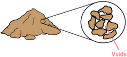
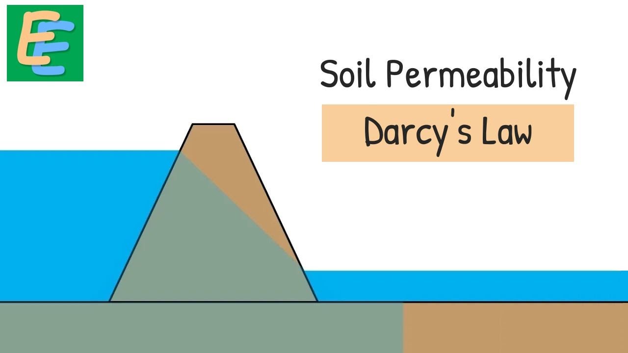
 Any soil when depositing contains some voids in them. The property of the soil which permits the water or any liquid to flow through it through its voids is called permeability. Permeability is the ease with which water can flow through the soils.
There are numerous methods through which we can measure the permeability of a soil in the field or of a representative sample in the laboratory.
In the laboratory we employ two methods
1. Constant Head Permeability Test
2. Variable Head or Falling Head Permeability Test

These tests measure the amount of water that goes through a soil sample in a fixed time interval.
Constant head method is suitable for coarse grained soils which are relatively more pervious because of their larger voids. While variable head is more suitable for small grained soils which are relatively less pervious because of their poorly connected void structure.
Let’s discuss Constant Head Permeability Method first.
We perform this test for granular soils, such as sand, where the quantity of discharge of liquid through them is large.
For this test to perform we use an instrument which is called constant head permeameter.
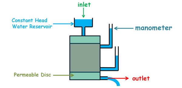
This instrument consists of a cylindrical mould which is connected with two manometers at its curved surface.
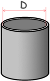
First we measure its internal diameter and determine its internal area which we say capital A.
This mould is attached with two filter discs at the top and the bottom. These discs are porous and highly permeable. These are also provided with inlet and outlet facilities
We can perform this experiment for both disturbed and undisturbed soil sample.
We fill the mould with our sample soil and compact it to a density which may be representative of the field conditions.
Or for an undisturbed sample we take out the soil sample from the ground and trim it to the dimensions similar to that of the mould. We place this sample inside the mould between porous discs. Some space will be left between the mould and the specimen that we will fill with some impervious material such as cement slurry.
The inlet of the instrument is then connected with a constant head water reservoir and water is released into the soil sample. When water flows through the soil, water level in the reservoir tend to decrease fast because soil we took is high permeability soil so high amount of water will flow through it. But with a proper arrangement the water level in the reservoir must be kept constant.
Before beginning the experiment we first let the soil sample get fully saturated and even after that we allow the water to flow out for some time so that a steady flow can be attained. A steady flow is the one in which the quantity of liquid flowing per second through any section, is constant.
We will also notice that after the water has been released into the soil, the water level in the manometers has risen up to some height.
The height of the water column in the manometer shows the total head or total energy of the water in the soil sample at this level.
 The difference in the heights of the water level in these two manometers is the difference of the total energy of the water at these two levels in the soil sample. This difference of energy of the water drives it to flow in the soil from the point of high energy to the point of low energy.
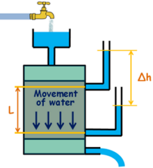
We note down the difference in the heads of these manometers as Δh and also note down the distance between the points in the soil where these heads were measured by these manometers as L.
We wish to maintain this difference of heads in the manometers so that we can maintain the hydraulic gradient inside the soil by keeping the head of the water reservoir constant.
We place a graduated jar at the outlet to collect the water coming out of the sample and a stopwatch is started. We collect the water in the jar for a fixed time internal t and note down the amount of water collected as Q.
Now for this system we may apply Darcy‘s law which state that the velocity of flow of liquid between two points in the soil is directly proportional to the hydraulic gradient applied to it.
v α i
and K is added as proportionality constant which is called coefficient of permeability of soil.
v = ki
We also write the law for discharge as this.
q = kAi
i is the hydraulic gradient and can be written as this.
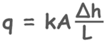
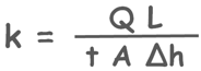
Here discharge can be calculated as volume of water collected Q divided by time interval t.
q = Q/t
We have calculated the area of mould A, we have also determined the head difference and the length L over which the head changed.
So we have measured all the required values in this equation to calculate and know the permeability of the soil sample.
According to Indian Standards we report the permeability values at 27 degree celcius temperature. So if we measure the temperature of the water as T degree Celcius then using this formula we can calculate the permeability at 27 degree celcius.
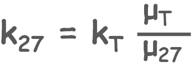
Here K27 is the permeability of the soil at 27 degree celcius
Here KT is the permeability of the soil at test temperature T degree celcius
myu T is coefficient of viscosity at temperature T
myu 27 is coefficient of viscosity at temperature 27 degree celcius


I am very happy but I want you sir to document give our free because this a huge probelm to sale this document in education.